The youtube video below, submitted in the J-WAFS video competition, does a good job of explaining the research in general.
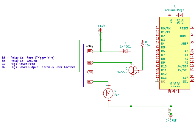
One of the initial schematics using the car relay to switch the fan and water pump on/off


We were using this relay with this schematic, but then replaced it with it with a simpler relay to avoid the extra circuitry.

We use the DS3231 RTC CLock to maintain an accurate Time Stamp.
Here is some example code to program/interface with the real time clock. Ignore the 32K and SQW lines, connect SDA and SCL lines to the Arduino, VCC to 5V and GND to GND.
We are using the BME280 Temperature/Humidity/Pressure Sensor We communicate with this sensor using I2C Protocol
Here is an picture overview of some of the electronics that are contained within the evaporative cooler.
Another picture showing the container and the the watertight seals for the outgooing and incoming cable connnections.
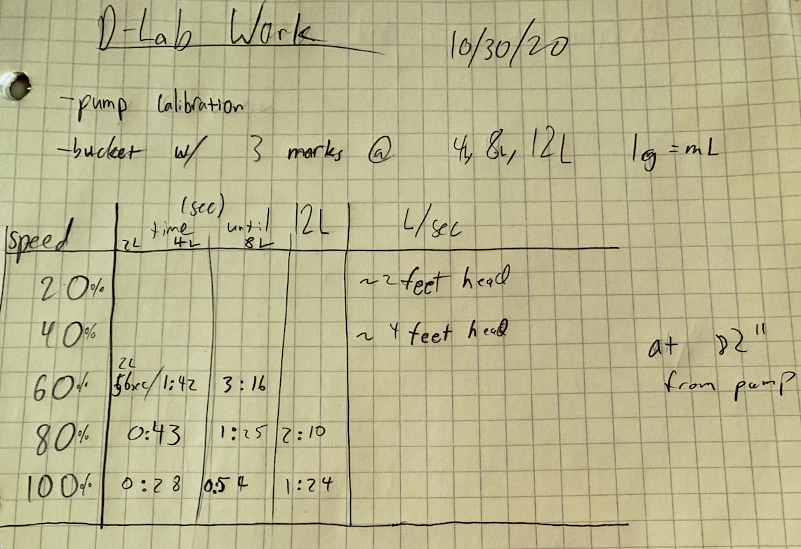
We went ahead and did a quantitative calibration for the water pump to see what voltages we needed to apply to get the output of water we desired.
At 20% and 40% voltage the water was not even able to go up the 82 inches to exit the tube.

More recently we have been working to get the data uploaded to a raspberrypi for easy remote access to the data.